09.03.2005
Content:
–Introduction
–What you need…
–Optical properties of water
–How the efffect is composed (Flow Chart)
–Rendering the reflection texture
–Rendering the refraction & depth texture
–Textures & Parameters
–The vertex program
–The fragment program
–GLSL conversion
–Updates(last Update:13.01.06)
–Links
Introduction
Before vertex & fragment shaders came out, it was very hard to simulate water. But now it is possible to render realistic water in realtime. Unfortunately, there isn’t much information on the internet for doing this. So I decided to write this tutorial. The algorithm presented here is best suited for small areas of water.
This tutorial doesn’t describe the basics of OpenGL, such as writing a base code or loading extensions, but everything you need for the water effect. I tried to keep things as easy as possible. Since this is my first tutorial, please send your feedback, questions or errors to 
*Update:Please use the comments to contact me*
What you need…
I assume that you have a normal map of the watersurface and the corresponding du/dv normal map. Of course, the quality of the water depends on the quality of the normal map.
du/dv normal maps
du/dv normal map are almost the same like standard normal maps. They are only red and green, this allows us to distort the texture coordinates of the reflection and refraction texture in the s and t directions by adding the du/dv normal map. ATi and Nvidia both have tools to generate du/dv normal maps from a height map.
Optical properties of water
When you look at real water, you will first notice the reflecting environment which is distorted by the waves. You will also see the environment under the water which is also distorted(caused by waves and refraction of the light). The distortion is the reason why we need a du/dv normal map.
The fresnel term (also called fresnel factor) tells us how much light reflects from the water surface. We will approximate the fresnel term with 1.0 minus the dot product of the pixel normal and the normalized vector to the camera position. We do this because it is faster and we don’t need each wavelength of the light.
In the nature there are many dirt particles floating within the water which cause a foggy look. To simulate this effect, we render the depth to a texture. This is also only an approximation but it works well.
And if the weather is good, you will also see specular highlights. That’s all!
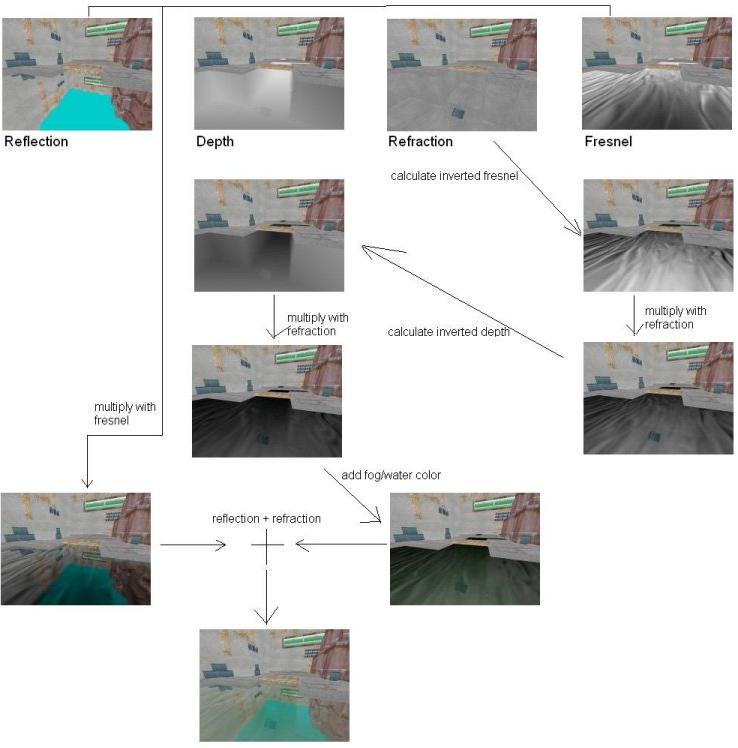
How the effect is composed
This Flow Chart shows how the effect is composed.
First the reflection, refraction and depth are rendered to textures. Then you calculate the fresnel factor and the depth, invert both and multiply the refraction with it. To give the water some color you add a fog/water color. The fog/water color is calculated by color*depth*inverted fresnel (not illustrated). After this the reflection is multiplied with the fresnel factor and added to the refraction.
Rendering the reflection texture
First we need to render our scene scaled by (1.0, -1.0, 1.0). This is our reflection texture, it is simply the scene turned upside down. The viewport has to be the same size as the reflection texture. Since we only want to render geometry above the water, we use glClipPlane to “cut off” everything else. Here’s some code:
//Render Scene scaled by(1.0, -1.0, 1.0) to texture
void RenderReflection()
{
glViewport(0,0, texSize, texSize);
glClear(GL_COLOR_BUFFER_BIT | GL_DEPTH_BUFFER_BIT);
glLoadIdentity();
gluLookAt(......)
glPushMatrix();
glTranslatef(0.0f, 0.0f, 0.0f);
glScalef(1.0, -1.0, 1.0);
double plane[4] = {0.0, 1.0, 0.0, 0.0}; //water at y=0
glEnable(GL_CLIP_PLANE0);
glClipPlane(GL_CLIP_PLANE0, plane);
RenderScene();
glDisable(GL_CLIP_PLANE0);
glPopMatrix();
//render reflection to texture
glBindTexture(GL_TEXTURE_2D, reflection);
//glCopyTexSubImage2D copies the frame buffer
//to the bound texture
glCopyTexSubImage2D(GL_TEXTURE_2D,0,0,0,0,0,texSize, texSize);
}
Rendering the refraction texture
Rendering the refraction is done almost the same way like the reflection. We don’t need the scaling, so we can leave it out. Then, the normal vector of the clip plane points in the opposite direction because we only want to render geometry under the water.
At the same time we also render the depth to texture. This way we can avoid another rendering pass.
 void RenderRefractionAndDepth()

{

glViewport(0,0, texSize, texSize);

glClear(GL_COLOR_BUFFER_BIT | GL_DEPTH_BUFFER_BIT);

glLoadIdentity();

gluLookAt(......)
glPushMatrix();
glTranslatef(0.0f, 0.0f, 0.0f);
//normal pointing along negative y
double plane[4] = {0.0, -1.0, 0.0, 0.0};
glEnable(GL_CLIP_PLANE0);
glClipPlane(GL_CLIP_PLANE0, plane);
RenderScene();
glDisable(GL_CLIP_PLANE0);
glPopMatrix();
//render color buffer to texture
glBindTexture(GL_TEXTURE_2D, refraction);
glCopyTexSubImage2D(GL_TEXTURE_2D,0,0,0,0,0,texSize, texSize);
//render depth to texture
glBindTexture(GL_TEXTURE_2D, depth);
glCopyTexImage2D(GL_TEXTURE_2D,0,GL_DEPTH_COMPONENT, 0,0, texSize,texSize, 0);
}
Textures & Parameters
Since we do all of the fun stuff with vertex & fragment programs, we just need to bind all of the textures and set some parameters when rendering the water. The variable texmove is an increasing value which we will add to the texture coordinates in the vertex shader to move the texture across the water.
 void RenderWater()

{
//bind & enable shader programs
glEnable(GL_VERTEX_PROGRAM_ARB);
glEnable(GL_FRAGMENT_PROGRAM_ARB);
glBindProgramARB(GL_VERTEX_PROGRAM_ARB, myVertexProgram);
glBindProgramARB(GL_FRAGMENT_PROGRAM_ARB, myFragmentProgram);
//move texture across water surface
glProgramLocalParameter4fARB(GL_VERTEX_PROGRAM_ARB, 0, texmove,texmove,texmove, 1.0f);
glProgramLocalParameter4fARB(GL_VERTEX_PROGRAM_ARB, 1, -texmove,-texmove,-texmove, 1.0f);
//Set viewposition and lightposition
glProgramLocalParameter4fARB(GL_VERTEX_PROGRAM_ARB, 2, viewpos.x,viewpos.y,viewpos.z, 1.0f);
glProgramLocalParameter4fARB(GL_VERTEX_PROGRAM_ARB, 3, lightpos.x,lightpos.y,lightpos.z, 1.0f);
//Set watercolor
glProgramLocalParameter4fARB(GL_FRAGMENT_PROGRAM_ARB, 0, water.red,water.green,water.blue, 1.0f);
//bind all textures
glActiveTextureARB(GL_TEXTURE0_ARB);
glEnable(GL_TEXTURE_2D);
glBindTexture(GL_TEXTURE_2D, reflection);
glActiveTextureARB(GL_TEXTURE1_ARB);
glEnable(GL_TEXTURE_2D);
glBindTexture(GL_TEXTURE_2D, refraction);
glActiveTextureARB(GL_TEXTURE2_ARB);
glEnable(GL_TEXTURE_2D);
glBindTexture(GL_TEXTURE_2D, normalmap);
glActiveTextureARB(GL_TEXTURE3_ARB);
glEnable(GL_TEXTURE_2D);
glBindTexture(GL_TEXTURE_2D, dudvmap);
glActiveTextureARB(GL_TEXTURE4_ARB);
glEnable(GL_TEXTURE_2D);
glBindTexture(GL_TEXTURE_2D, depth);
//Render the water surface
glBegin(GL_QUADS);
glMultiTexCoord2fARB(GL_TEXTURE0_ARB, 0.0f, 5.0f);
glMultiTexCoord2fARB(GL_TEXTURE1_ARB, 0.0f, 1.0f);
glMultiTexCoord2fARB(GL_TEXTURE2_ARB, 0.0f, 1.0f);
glMultiTexCoord2fARB(GL_TEXTURE3_ARB, 0.0f, 1.0f);
glMultiTexCoord2fARB(GL_TEXTURE4_ARB, 0.0f, 1.0f);
glVertex3f(-5.0f, 0.0f, 5.0f);
glMultiTexCoord2fARB(GL_TEXTURE0_ARB, 0.0f, 0.0f);
glMultiTexCoord2fARB(GL_TEXTURE1_ARB, 0.0f, 1.0f);
glMultiTexCoord2fARB(GL_TEXTURE2_ARB, 0.0f, 1.0f);
glMultiTexCoord2fARB(GL_TEXTURE3_ARB, 0.0f, 1.0f);
glMultiTexCoord2fARB(GL_TEXTURE4_ARB, 0.0f, 1.0f);
glVertex3f(-5.0f, 0.0f, -5.0f);
glMultiTexCoord2fARB(GL_TEXTURE0_ARB, 5.0f, 0.0f);
glMultiTexCoord2fARB(GL_TEXTURE1_ARB, 0.0f, 1.0f);
glMultiTexCoord2fARB(GL_TEXTURE2_ARB, 0.0f, 1.0f);
glMultiTexCoord2fARB(GL_TEXTURE3_ARB, 0.0f, 1.0f);
glMultiTexCoord2fARB(GL_TEXTURE4_ARB, 0.0f, 1.0f);
glVertex3f(5.0f, 0.0f, -5.0f);
glMultiTexCoord2fARB(GL_TEXTURE0_ARB, 5.0f, 5.0f);
glMultiTexCoord2fARB(GL_TEXTURE1_ARB, 0.0f, 1.0f);
glMultiTexCoord2fARB(GL_TEXTURE2_ARB, 0.0f, 1.0f);
glMultiTexCoord2fARB(GL_TEXTURE3_ARB, 0.0f, 1.0f);
glMultiTexCoord2fARB(GL_TEXTURE4_ARB, 0.0f, 1.0f);
glVertex3f(5.0f, 0.0f, 5.0f);
glEnd();
//Disable texture units and shader programs
.
.
.
}
The vertex program
First we need to set some parameters:
!!ARBvp1.0
PARAM mvp[4] = {state.matrix.mvp}; #modelview projection matrix
PARAM mtx[4] = {state.matrix.texture[0]}; #texture matrix
#needed for texture movement
#time = texmove, time2 = -texmove
PARAM time = program.local[0];
PARAM time2 = program.local[1];
PARAM viewpos = program.local[2];
PARAM lightpos = program.local[3];
#tangent space. depends on texcoords
PARAM tangent = {1.0, 0.0, 0.0, 0.0};
PARAM bitangent = { 0.0, 0.0, 1.0, 0.0};
PARAM normal = { 0.0, 1.0, 0.0, 0.0};
TEMP vpos, temp;
Then we need the tangent space vector to the view position and light position
#get vector to view position

SUB temp, viewpos, vertex.position;

#calculate the tangent space vector to view position

#and store in texture coordinates from texture unit 4
DP3 result.texcoord[4].x, temp, tangent;
DP3 result.texcoord[4].y, temp, bitangent;
DP3 result.texcoord[4].z, temp, normal;
MOV result.texcoord[4].w, 1.0;
#same procedure with the vector to the light position
SUB temp, lightpos, vertex.position;
DP3 result.texcoord[0].x, temp, tangent;
DP3 result.texcoord[0].y, temp, bitangent;
DP3 result.texcoord[0].z, temp, normal;
MOV result.texcoord[0].w, 1.0;
Now some basic stuff. We don’t put the transformed vertex position directly in result.position because we need it again.
#transform vertex coords to clip coords

DP4 vpos.x, mvp[0], vertex.position;

DP4 vpos.y, mvp[1], vertex.position;

DP4 vpos.z, mvp[2], vertex.position;

DP4 vpos.w, mvp[3], vertex.position;

MOV result.position, vpos;
The textures are moved acrossed the water by adding an increasing value to the tex coords.
 ADD result.texcoord[1], vertex.texcoord[0], time;

#move in opposite direction

ADD result.texcoord[2], vertex.texcoord[0], time2;
We need to calculate our own projective tex coords. The first step is to multiply our vpos with the texture matrix. The other step will be made in the fragment program.
 DP4 result.texcoord[3].x, mtx[0], vpos;

DP4 result.texcoord[3].y, mtx[1], vpos;

DP4 result.texcoord[3].z, mtx[2], vpos;

DP4 result.texcoord[3].w, mtx[3], vpos;
#don't forget END
END
The fragment program
Now it’s time for the fun part. Again, we first have to set some parameters and temporary variables.
!!ARBfp1.0
#scale factors for du/dv normalmaps
PARAM scale = { 0.005, 0.005, 0.005, 0.005};
PARAM scale2 = { 0.02, 0.02, 0.02, 0.02};
#scale factor for tex coords
PARAM tscale = {0.5, 0.5, 0.5, 0.5};
PARAM two = {2.0, 2.0, 2.0, 2.0};
PARAM mone = {-1.0, -1.0, -1.0, -1.0};
#specular exponent
PARAM exp = 128.0;
#"fog" exponent
PARAM fexp = 4.0;
PARAM watercolor = program.local[0];
TEMP reflection, refraction;
TEMP depth, invdepth;
TEMP fresnel, invfresnel;
TEMP normal, invLen, viewts, lightts;
TEMP disdis, dist, ntc, specular, lref;
TEMP projb, temp, temp2;
We normalize the vector to the light and the vector to the view position
 #normalize light vector

DP3 temp, fragment.texcoord[0],fragment.texcoord[0];

RSQ invLen, temp.x;

MUL lightts, fragment.texcoord[0], invLen;
#normalize vector to viewpos
DP3 temp, fragment.texcoord[4],fragment.texcoord[4];
RSQ invLen, temp.x;
MUL viewts, fragment.texcoord[4], invLen;
Then we load the du/dv normalmap for the first time. Since it would look static if we just move the normalmaps across the surface, we load the du/dv normalmap with tex coords moving in the opposite direction and add them to the normal tex coords. This way you get the look of random waves on the water.
 #distortion distortion

MUL temp, fragment.texcoord[2], tscale; #scale tex coords

TEX disdis, temp, texture[3], 2D; #load du/dv normalmap

MUL disdis, disdis, scale2; #scale colors down
#Add distortion to texcoord 1
ADD temp2, fragment.texcoord[1], disdis;
The distorted tex coords for the normalmaps are stored in temp2. We are now ready to load both normalmaps.
 #load normalmap with new texcoords

TEX normal, temp2, texture[2], 2D;

MAD normal, normal, two, mone; #scale and bias

#normalize

DP3 temp, normal, normal;

RSQ invLen, temp.r;

MUL normal, normal, invLen;
#load du/dv normalmap
TEX dist, temp2, texture[3], 2D;
MAD dist, dist, two, mone;
MUL dist, dist, scale;
With the normalmap we calculate the light reflection vector. The equation for the reflection vector is 2*dot(normal, lightts)*normal – lightts. We need it later for the specular highlight.
 DP3 temp, normal, lightts;

MUL temp, temp, two;

MUL temp, temp, normal;

SUB lref, temp, lightts;

#normalize reflection vector DP3 temp, lref, lref; RSQ temp, temp.x; MUL lref, lref, temp;
Do you remember our first step for calculating projective tex coords in the vertex program? It’s time for the other step now. When we calculated the tex coords, we distort them by adding the scaled du/dv normalmaps.
 #calculate projective texcoords

#divide by w component

RCP temp, fragment.texcoord[3].w;

MUL projb.x, fragment.texcoord[3].x, temp.x;

MUL projb.y, fragment.texcoord[3].y, temp.y;

MUL projb.z, fragment.texcoord[3].z, temp.z;

ADD projb, projb, {1.0, 1.0, 1.0, 1.0};

MUL projb, projb, {0.5, 0.5, 0.5, 0.5};
#add distortion to
#projective tex coords
ADD ntc, projb, dist;
It is possible that ntc is out of the range [0.0, 1.0]. This causes black artifacts at the borders of the screen. We solve this problem by clamping ntc to the range [0.001, 0.999].
 MIN ntc, ntc, 0.999;

MAX ntc, ntc, 0.001;
We are ready to load the reflection, refraction and depth texture.
 #load reflection and refraction with new texcoords

TEX reflection, ntc, texture[0], 2D;

TEX refraction, ntc, texture[1], 2D;
#load depth texture
TEX depth, ntc, texture[4], 2D;
To get more contrast in the depth texture, we calculate depthfexp. The smaller fexp, the foggier the water. The inverted depthfexp tells us where the water is foggy.
 #calculate depthfexp

POW depth, depth.x, fexp.x;
#invert depth
SUB invdepth, 1.0, depth;
Now we calculate the specular highlight.
 DP3 specular, lref, viewts;

POW specular, specular.x, exp.x;

MAX specular, specular, 0.0;
We are almost done with the “preparations”. Before we finally start with the main part of this program, we need the fresnel term and the inverted fresnel term.
 #calculate fresnel

DP3 invfresnel, normal, viewts;

SUB fresnel, 1.0, temp;
All factors we need are available now.
We first modulate the refraction with the inverted fresnel and then with the inverted depth. This gives us all parts on the surface where we see the refraction texture.
 MUL refraction, refraction, invfresnel;

MUL refraction, refraction, invdepth;
Now we add some color. Since we only want the foggy parts to be green, we modulate the watercolor with depthfexp. The result is then modulated with the inverted fresnel, to get the non-reflective parts, and added to the refraction texture.
 MUL temp, watercolor, depth;

MUL temp, temp, invfresnel;

ADD refraction, refraction, temp;
The refraction texture is finished. The reflection texture is then modulated with the fresnel to get only the reflective parts. We just add the reflection and the refraction and our water is almost complete. The last thing we need to do is to add specular highlight.
MUL reflection, reflection, fresnel;
ADD temp, reflection, refraction;
ADD result.color, temp, specular;
END
That’s it. Your main rendering function should look like this:
 void Render()

{
RenderReflection();
RenderRefractionAndDepth();
//reset viewport to screensize
glViewport(0,0, screen_width, screen_height);
glClear(GL_COLOR_BUFFER_BIT | GL_DEPTH_BUFFER_BIT);
glLoadIdentity();
gluLookAt(......);
RenderScene();
RenderWater();
}
GLSL conversion
A GLSL conversion of the vertex & fragment program is available in the forum:
Discuss this tutorial in the forums
Updates
11.03.05 – vertex.texcoord[5] and fragment.texcoord[5] were used although the the fifth texture unit wasn’t used. Changed both to .texcoord[0] and removed
MOV result.texcoord[0], vertex.texcoord[0];.
Remember to generate your reflection, refraction and depth textures in your initialization-code before rendering the scene to them.
23.03.05 – The clip plane in the RenderReflection() function was enabled and set before the scaling. It has to be set after glScalef() to give correct results.
13.08.05 – Fixed small errors. Added links to texture tools. The tangent vectors now have correct values.
24.08.05 – GLSL conversion posted
13.01.06 – Added flow chart.
Added normalization of light reflection vector in the fragment program and fixed specular lighting equation. Without the normalization black artifacts appeared on Nvidia cards.
Last Update: Please check the forum for future updates.